DESIGNING A 3D-PRINTED RC PLANE: PART 2
Last time we left off, we had a direction and these objectives
- [ ] Finalize the sub-250 gram b.o.m. and order parts.
- [ ] Create bounding box template for components.
- [ ] Design and model airframe
As I dug further into component selection, it became apparent that the sacrifices necessary to hit that 249g weight goal with EDFs are substantial. We'll dig into how I came to this conclusion later on.
For a first build, I'm going to take the "easier" route with a slightly heavier but still single engined-plane, enabling the addition of GPS and 4k video feeds on a 2 axis camera gimbal with head tracking. We'll set our weight limit at 750g based on an established plane. First, let's redefine our short-term goals, and then take a deep dive into our bill of materials.
- [x] Finalize the sub-750 gram b.o.m. and order parts.
- [ ] Create bounding box template for components.
- [ ] Assemble components.
Here is our finalized B.O.M.
| Category | Item | Weight | Cost |
|---|---|---|---|
| [ AIRCRAFT ] | |||
| Propulsion | XFly 50mm Galaxy X5 EDF | 76g | $28.99 |
| ESC | STRIX Rocket 65A OPTO | 32g | $26.79 |
| Servos | FMS 9g Digital MG (x4) | 36g | $23.98 |
| Battery | Tattu 1800mAh 4S 120C | 193g | $49.99 |
| Airframe | Bambu Lab ASA-Aero | ~280g | $49.99 |
| Flight Control | Speedybee F405-Mini | 10g | $65.99 |
| Receiver | Radiomaster RP1 ELRS | 8.5g | $23.99 |
| FPV Camera | Walksnail Moonlight Kit | 6g | $180.00 |
| FPV Gimbal | XFly Pan-Tilt Mount | 13g | $26.99 |
| Structural | 6mm 3K Carbon Tube | 25g | $23.80 |
| GPS | BZG NSS BZ-251 GPS | 12g | $23.80 |
| AIRCRAFT PROTOTYPE SUBTOTAL | ~719.5g | $500.51 | |
| [ GROUND ] | |||
| FPV Goggles | Walksnail Goggles X | -- | $459.99 |
| Transmitter | Radiomaster Pocket ELRS | -- | $82.99 |
| Power (Ground) | 18650 Batteries (2-pack) | -- | $14.99 |
| Smart Charger | IMARS D300 Dual Channel | -- | $32.99 |
| Adapter | DIY 18650 2-Slot Sled | -- | $17.99 |
| GROUND SYSTEMS SUBTOTAL | $608.95 | ||
| [ WORKSHOP ] | |||
| Wiring | 14AWG & 28AWG Kits | -- | $22.96 |
| Connectors | XT60 Pigtails (5 Pairs) | -- | $10.99 |
| Soldering | Kester 44 Rosin Core | -- | $13.23 |
| WORKSHOP & CONSUMABLES SUBTOTAL | $47.18 | ||
| TOTAL COMBINED PROJECT INVESTMENT | ~$1,156 | ||
The process from starting research to finalizing the bill of materials took about 125 hours. At about 100 hours and 5 "finalized" builds I had dug into and abandoned, I realized there must be a better way. I grabbed a Gemini Pro subscription and began work on RCForge, an app that will serve as an evolving RC design accelerator. First we created a deep parts catalog. We scraped data on anywhere from 6 to 19 models of each of the following: EDFs, FCs (Flight controllers), ESCs (Electronic speed controllers), FPV (First-Person-View) cameras, FPV camera gimbals, FPV goggles, servos, batteries, transmitters, receivers, BECs (Battery Eliminator Circuits). This data includes dimensions, specs, cost, compatibility across selection, and hyperlinks.
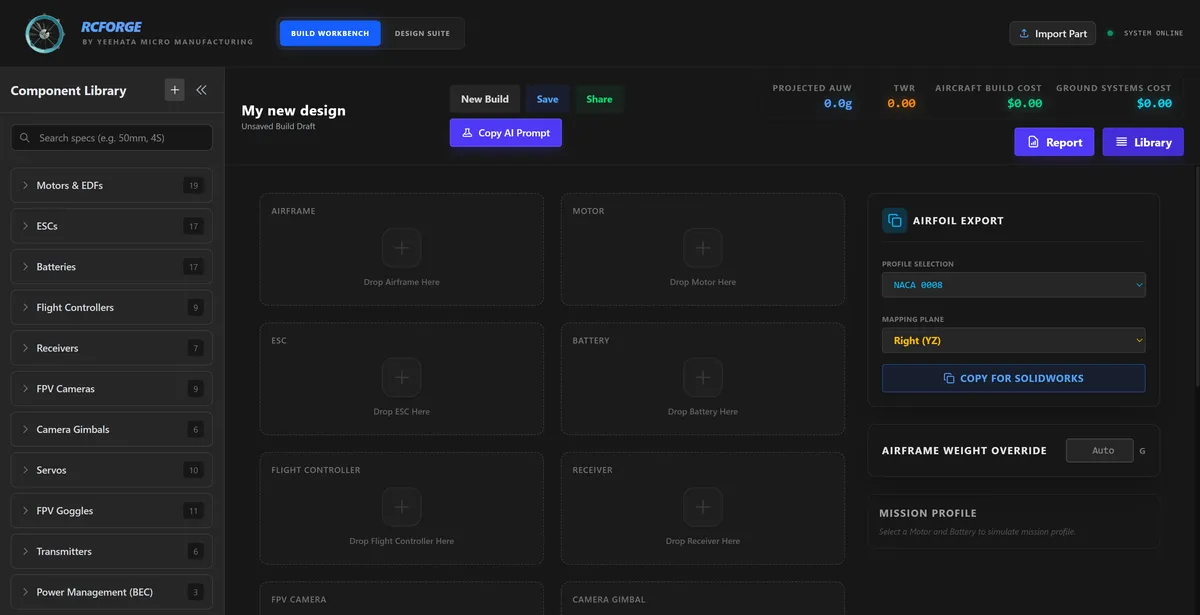
We built the frontend in Tauri and backend in Rust for fast response-time and windows/linux compatibility. After a week of adding features and a ground-up rebuild, our feature list for RCForge now includes:
- Assemble RC plane by component selection
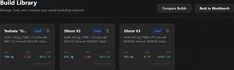
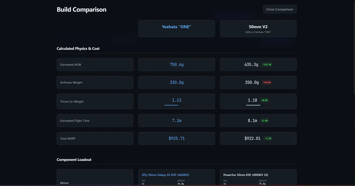
- Save and compare every spec of multiple builds
- Override weight for early-stage airframe design
- Generate airfoil coordinates for quickly importing airfoil shapes into SolidWorks
- Automatically generate detailed build reports with high-level wiring diagrams
Generating various builds in RCForge, I realized durability would be a significant challenge given the tiny fuselage weight limit. I would also have to sacrifice an FPV gimbal, which I consider paramount to maximizing the fun and immersion of the system. Instead, we're going to find the best 50mm EDF FPV plane for some baseline specs, and then try to improve it in every way. Our limit is 750g (1.65lbs) AUW (All Up Weight). This leaves approximately 340g for the 3D-printed fuselage (~25g carbon spar not included). We will choose the most powerful 50mm EDF you can buy, the XFly 50mm Galaxy X5, which produces 900g of thrust. Based on some napkin calculations, the fan rotor of this EDF will spin at 60,000 - 65,000 RPM. That boggles my mind and makes the monkey with cymbals in my head start clapping with joy. Anyway... Now that we know the weight limit and motor, we can drive every other decision from them.
The Physics of Flight: Sizing the Yeehata MONO
To ensure our 750g prototype doesn't take its first flight directly into the ground, we have to balance three critical areas of aerospace design: Wing Loading, Fuselage Volume, and Duct Efficiency.
1. Wing Design: The Lift Equation
To determine how much wing surface area (S) we need to stay airborne at a reasonable speed, we use the Lift Equation:
L = ½ ρ v² S CL
- L (Lift): Must equal our weight (~7.35 Newtons for 750g).
- ρ (Air Density): ~1.225 kg/m³ at sea level.
- v (Velocity): Our target stall/landing speed.
- CL (Lift Coefficient): Dependent on our airfoil shape (generated in RCForge).
For a 3D-printed plane using ASA-Aero, we want to keep our Wing Loading (W/S) between 40–60 g/dm². Anything higher and the plane becomes a lawn dart that requires a massive amount of speed to stay in the air, making landings sketchy and stressful.
2. Fuselage Volume & Bounding Boxes
Because 3D-printed airframes are rigid, we can't just jam components in like a foamie. We use a Bounding Box Volume calculation to ensure the internal cavity can actually house the electronics:
Vreq = Σ (Vcomp + Vclearance)
In SolidWorks, I create a Master Sketch using these bounding boxes. If the total internal volume (Vreq) exceeds the aerodynamic profile of our fuselage, we increase the scale. At 750g, we have enough mass to allow for a wider fuselage, which is necessary to accommodate the Walksnail Moonlight Kit and the XFly Pan-Tilt gimbal.
3. The EDF Secret: Ducting and FSA
With an EDF, the "Fan Swept Area" (FSA) is the most critical metric for performance. It is the area of the fan circle minus the area of the motor hub:
FSA = π (Rfan² - Rhub²)
To maximize our 900g of thrust from the Galaxy X5, our ducting must follow the Rule of 100/85:
- Intake Area: Should be 100% to 110% of the FSA to ensure the fan isn't "starved" for air.
- Exhaust (Nozzle) Area: Should be tapered to 85% of the FSA. This increases the exhaust velocity (the "jet" effect), giving us a higher top speed at the cost of some static thrust.
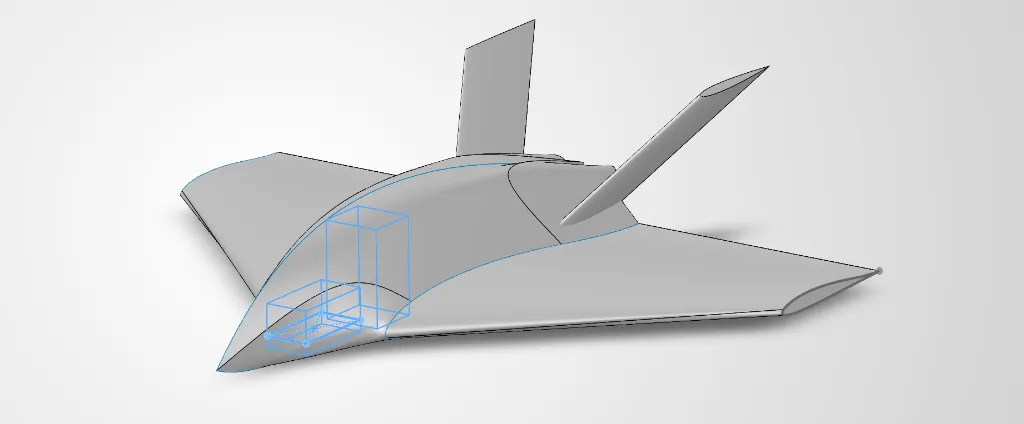
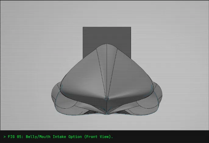
As I've begun to dig into modeling the "ONE" in SolidWorks, I'm finding the process extremely slow for the current stage of the build. Initially, I was planning for a top-mounted dorsal intake for the EDF, but the need for the Battery and FPV Gimbal to sit in the nose/cockpit section of the plane means we'd be putting a large obstruction right in front of the intake - adding not only parasitic drag but turbulent air to our turbine, reducing its power and efficiency. As such, there must be a better way! It seems there are two options, then. The first is a belly/mouth intake which flows under the components in sealed ducting and then curves up behind the gimbal and above the carbon wing spar (Think F-86 Sabre/LTV A-7 Corsair II.) The second is dual side-mounted intakes which flow around the outside of the battery, gimbal, and FC and join into a single duct.
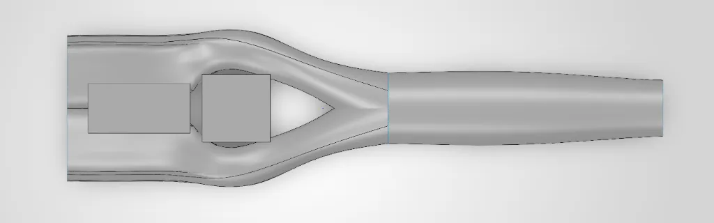
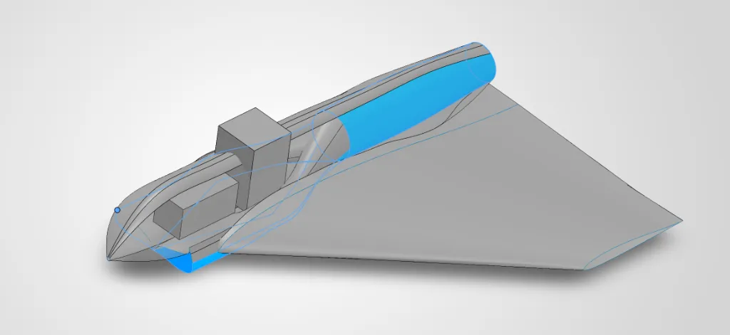
My first (and only, so far) attempt at modeling the ducts was a mix of 1 and 2. They were twin intakes that wrapped around the nose, but I've found a considerable challenge in properly mating the two ducts into one without creating serious aerodynamic problems (the intake curves must be very smooth and shallow.) I've spent the last 3 hours attempting to find workarounds without success, so it seems like an appropriate time to stop and evaluate if this is actually what we want. A good ole fashioned pros and cons list should do the trick.
Option 1 (Belly/Mouth Intake)
- Pros: simpler/easier ducting
- Cons: potential stall at high AoA (Angle of Attack), adds unnecessary length to intake ducts if stall risk is mitigated through very forward-mounted intake
Option 2 (Twin Side Intakes)
- Pros: better flight envelope, less stall risk at high AoA, allows us to slightly shrink the airframe
- Cons: more difficult ducting to model, adds more curves for the air to navigate
Sidenote: I'm questioning if SolidWorks is the right tool for the job here. I know this process could be massively automated to remove pain points, time sinks, and enable faster design exploration. In my research I've come across OpenVSP, an old NASA aircraft design tool which appears even more ancient. But lucky for us, it's an open source tool! It's a bit of a moonshot, but I'm going to see if some AI agents can help me refactor OpenVSP into a fast, modern, and intelligent tool for accelerating design. OpenVSP already has CFD analysis, loading testing, and a host of other tools which will be useful in building this dream.
The dream: to quickly realize an aircraft design, select your parameters to optimize, and run Monte Carlo simulations to determine a host of potential efficiency improvements. We've got 2-4 weeks before all parts arrive, so we'll give 20-40 hours to this project in parallel to traditional modeling and reassess after that. Until next time...
COMMENTS_CHANNEL
No comments yet. Be the first transmission.