DESIGNING A 3D-PRINTED RC PLANE: PART 3
Last time we left of, we were in the thick of intake design trade-offs. Let's dive right back in..
Twin Intakes Win by Elimination
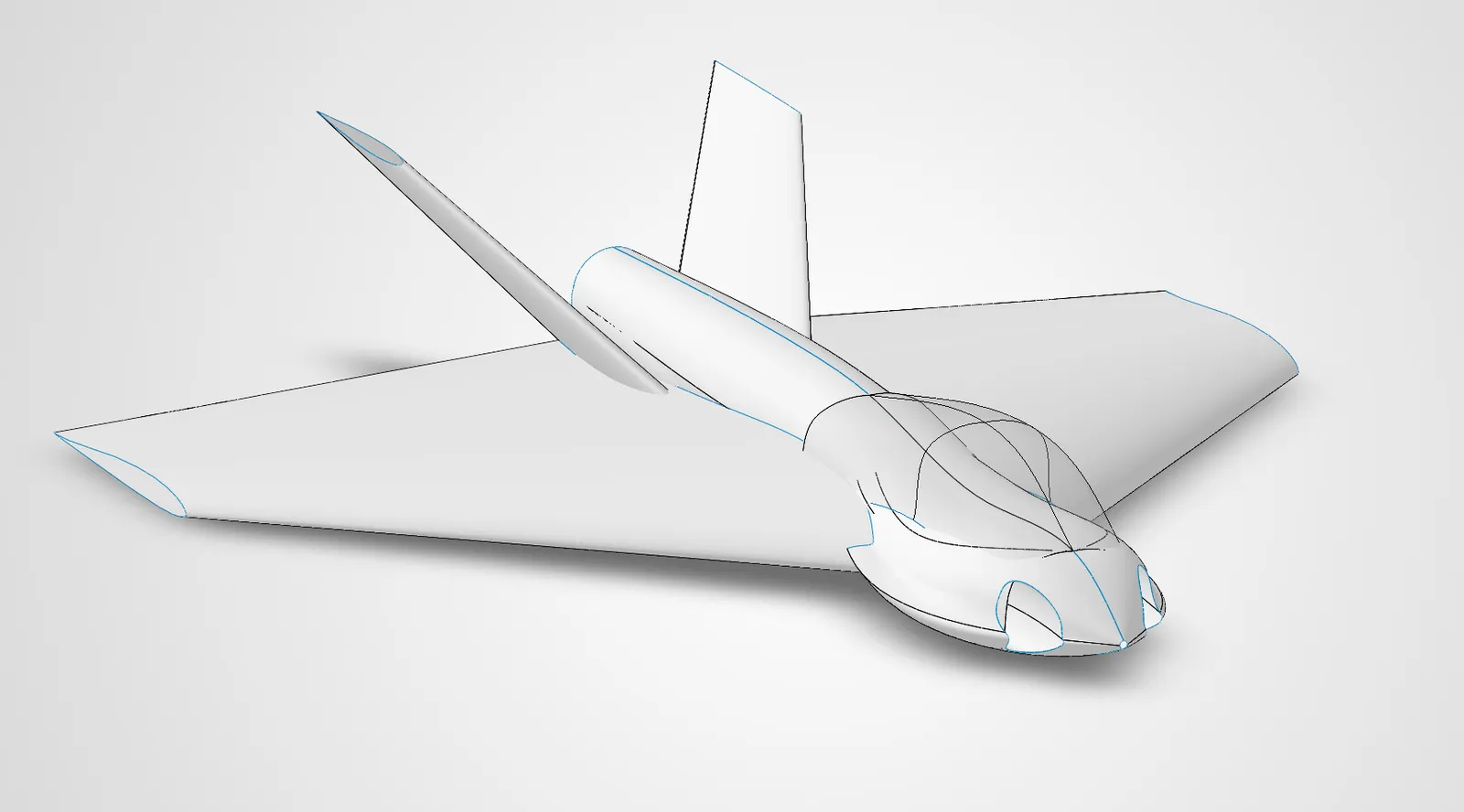
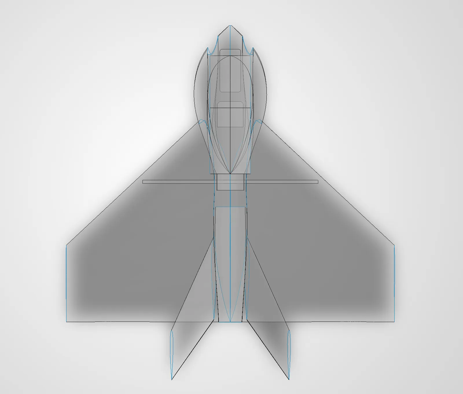
We've decided that the top-mounted dorsal intake is a dead end. This is due to the desire to have a top-mounted gimbal - this would create a wake of turbulent air right in front of the intake, and height constraints don't allow for proper stacking. The belly intake is also dead on arrival, as our lack of landing gear would mean our EDF will suck up debris on landing and likely damage the EDF blades, housing and/or motor. This leaves us with twin side intakes. Given the extensive electronic suite we've selected for the build, we're going to be generating considerable amounts of heat - and thus proper heat management becomes a non-negotioable requirement. My first thought is to mount the intakes flush with the nose of the plane, just to the side of the leading point in an attempt to accomplish three goals simultaneously:
- avoid intake "choking" that is caused by the boundary layer that forms around the skin of the aircraft.
- run the ducting completely internally with thin walls around the flight systems, providing passive cooling due to the fast moving ducted air.
- remove draggy external intakes
RCForge work has slowed and transitioned into a new tool CFDForge - attempting to tie in the real-time lattice Boltzmann CFD software with a rapid design tool like openVSP for rapid and "informed" design exploration. Unfortunately, this project requires too many prerequisites I don't possess at the moment so it will be shelved until I've spent a considerable time learning, and my AI tools make another 10x improvement. Let's get back to CAD and gain an actual grasp on these surfacing tools so we can solve our duct-surfacing-woes.
Surfacing Lessons Learned the Hard Way
If you're just beginning to use surfacing tools in SolidWorks, here are a few things I wish I knew -
- The defaulted guide points are wrong almost every time. Often, your surface preview won't even render becuase of the poor default placement of these. Play with the placement of these before backing out of the surface tool for the 6th time to check your reference drawings.
- Ensure your reference drawings intersect. You must check from many different vantage points.
(For aircraft design specifically)
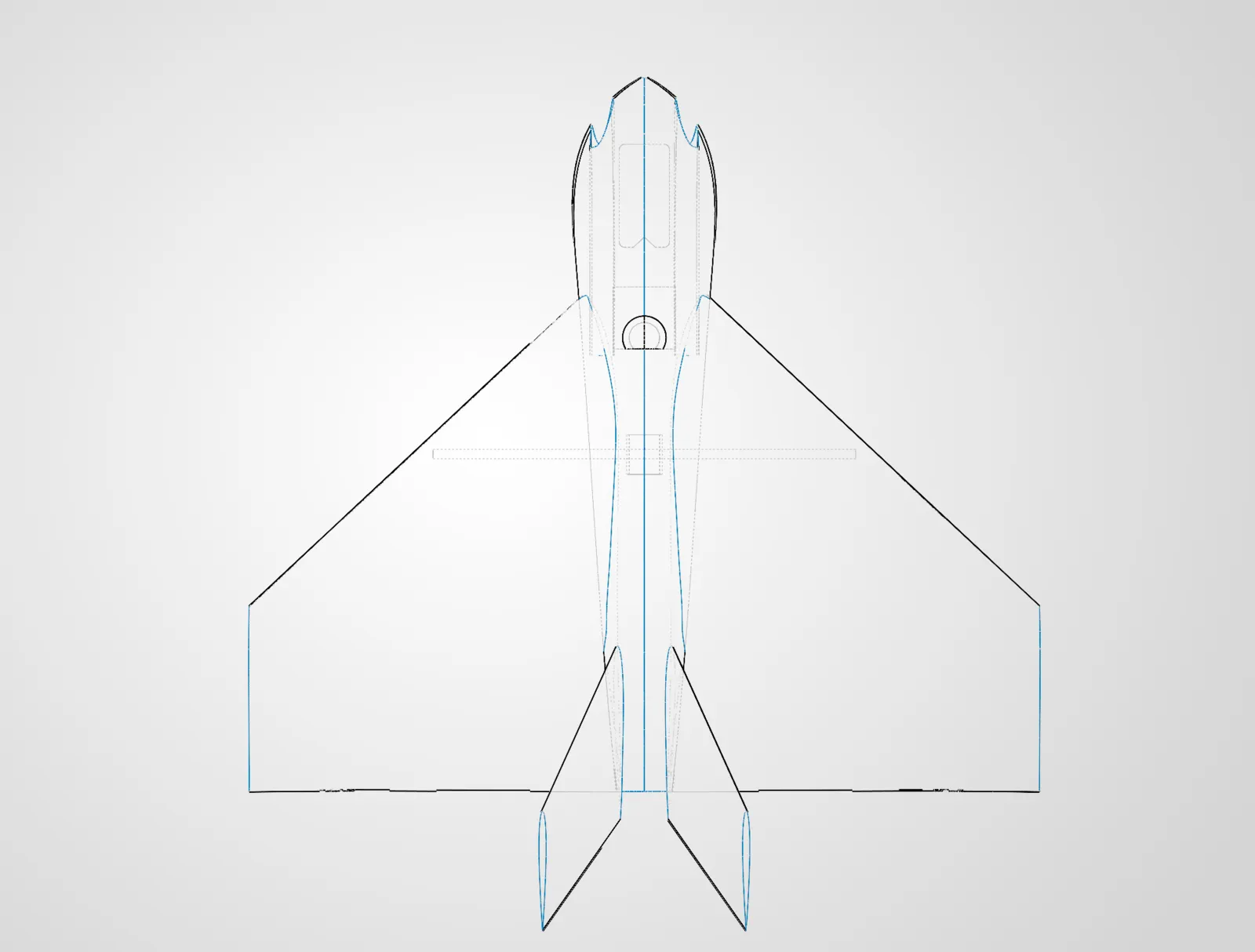
- When drawing fuselage ribs, use construction lines for the vertical origin axis to avoid creating unintentional internal walls when mirroring.
- When editing your airfoil sketch, if your chosen airfoil has a sharp trailing edge, you must cut the trailing edge of the airfoil off with at least 1.6mm between the upper and lower trailing edges(If you're using .8mm layer lines). When you thicken the surface later, this will give you the required space for two layer lines of thickness at .8mm without the feature intersecting itself and failing.
Canopy Trade-Offs
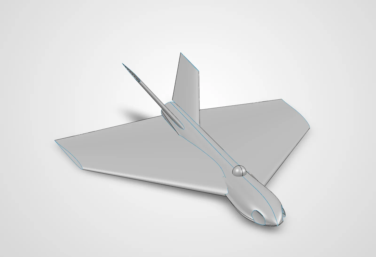
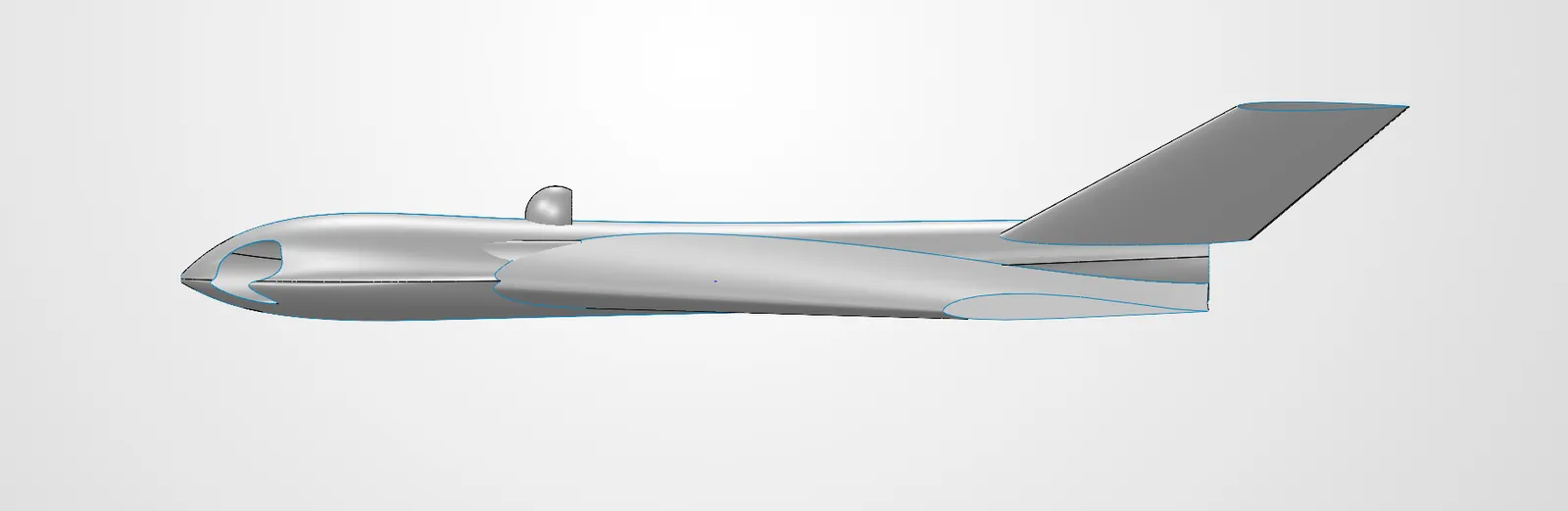
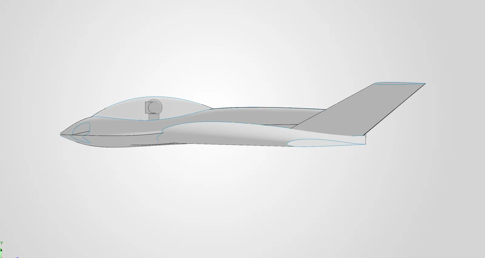
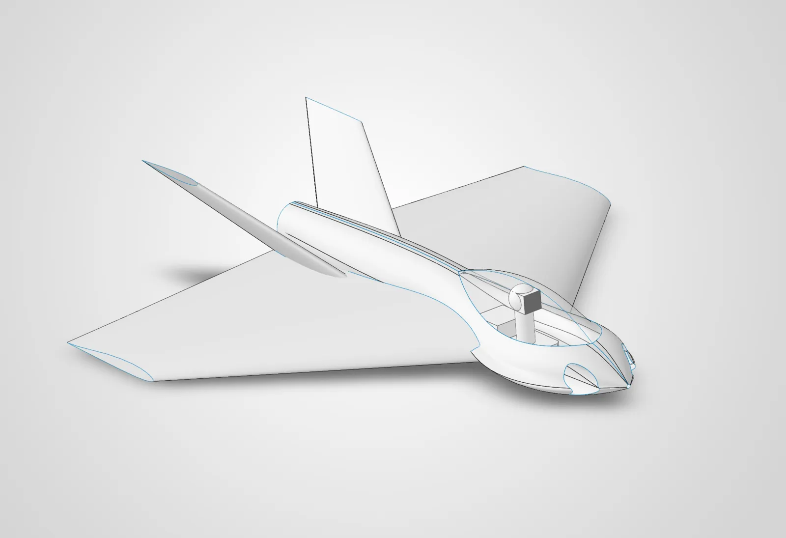
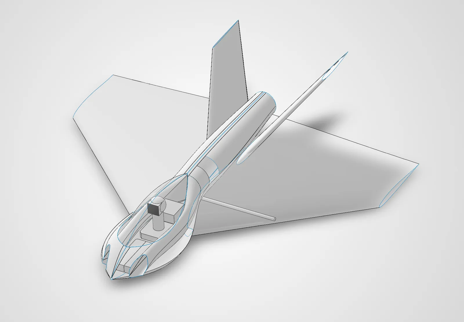
After a week-long CAD and learning marathon, we've got a fuselage finally taking shape. We're now at a crossroads for our gimbal placement and design. As part of the extreme-durability goal, there's a heavy incentive to encase the expensive camera and gimbal in a clear canopy. Unfortunately, I don't yet have an SLA printer capable of printing a clear enough canopy. So, we're going to have to get creative.
Our options (as I see them now) with pros and cons are
-
1. buy a premade canopy from someone else
pros: saves time and effort
cons: likely expensive, may be difficult to find correct dimensions, constrains airframe design to someone else's part, adds potential future supply chain failure point
-
2. print a high-temp mold out of engineering filament, and then get sheets of PETG or similar and use a heat gun or oven to form them
pros: never made a printed mold, good learning opprotunity, allows endless cheap iteration,
cons: potentially unreliable results, extensive time and tooling investment
-
3. design it myself and have it printed by a fellow maker/service with SLA
pro: future proofs, allows me to eventually take the task in-house once SLA printer is acquired, potential for collaboration
cons: delays in design with every iteration change, potentially high cost if I can't offer anything in return
-
4. find a way to recycle old plastic bottles into canopies.
pros: cool as hell, pro-nature
cons: potentially janky, reflections?
For now, we'll design it and hope that leads to more clarity on the design decision. Things are starting to look pretty good.

System Failure
At about 11:56pm, just about to save and conclude a 15 hour design sprint aaaand SolidWorks freezes and crashes. I gasp. I hadn't saved in hours (c'mon dude what're u doing), had made probably a hundred changes and fixes in that time, and now our file is corrupted. Well, at least solidworks is still working. Wait, SolidWorks won't even open. This is a disaster... for tomorrow.
Tomorrow came, and SolidWorks was still dead. A hotfix started spreading through the forums, but didn't work for me. 30 some-odd hours later, a working hotfix is released, and my file is still corrupted. This sucks. I need a cigarette.
Once the dust settled, I realized my "Feature Tree of Doom" being gone was a blessing, and this was a prime opprotunity to rebuild in a simpler, more intelligent way. We'll take a beat, gather our thoughts, revisit our assumptions, and start the redesign.
COMMENTS_CHANNEL
No comments yet. Be the first transmission.